Spiro Gear
Choosing the right Geared Motor in 2026 requires more than comparing price, wattage, or catalogue size. The correct choice must match the machine’s real working conditions. Consider output torque, operating speed, duty cycle, starting load, efficiency, noise, backlash, and thermal limits. A motor that looks powerful on paper may overheat during repeated starts. A compact unit may fail when dust, moisture, or shock loads are ignored.
Professor Peter R. N. Childs, author of Mechanical Design Engineering Handbook, expresses a valuable engineering principle: “Design should begin with requirements, not with preferred components.” This idea remains highly relevant for Geared Motor selection. Begin with the driven load, not the motor shelf. Measure the shaft speed and torque. Record acceleration time, daily operating hours, stopping frequency, and ambient temperature. Then check service factors, gearbox ratio, mounting position, insulation class, and IP protection.
IEC 60034 ratings can support a more reliable comparison, but they cannot answer every practical question. Supplier data may use different testing conditions. That detail is easy to miss. Ask for efficiency curves, permissible radial loads, thermal data, and maintenance guidance. Helical, planetary, worm, and bevel designs each bring trade-offs. Worm gearboxes may offer strong reduction, yet often lose more energy through heat.
A good selection is rarely perfect. It is a defensible balance between performance, cost, space, and future risk. Recheck assumptions before approving the purchase. The smallest mistake may appear months later as noise, heat, or unexpected downtime.
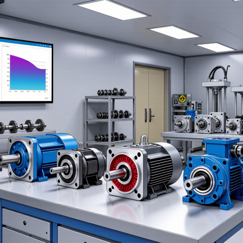
How to Choose the Right Geared Motor in 2026?
Define the Application Requirements for a Geared Motor
Choosing a geared motor starts with the machine, not the catalogue. Describe the real movement, load, and working environment before comparing models. Measure the required output speed in revolutions per minute. Record the continuous torque and the highest starting torque. A conveyor carrying 80 kilograms may need much more torque during acceleration than during steady movement.
Measure it.
Include the duty cycle, because a motor running for two minutes differs from one operating all day. Note the number of starts per hour, reversing frequency, and expected service life. Check the available power supply, mounting position, shaft direction, and allowable noise. For vertical lifting, calculate the holding requirement carefully. Gravity does not forgive a weak estimate.
Environmental details also affect the gearbox selection. Dust, moisture, heat, washdown procedures, and limited ventilation can change the required enclosure and lubrication approach. Consider shock loads from sudden stops or uneven products. A practical safety factor is useful, but an excessive factor may create unnecessary cost and poor efficiency. Fit matters.
I have seen projects fail because the designer used the rated load instead of the actual starting load. That mistake looks small on paper. It becomes obvious when the motor overheats or stalls. Recheck calculations with measured data, then confirm the gearbox can handle radial and axial shaft forces. The first estimate is rarely perfect. Leave room for honest revision.
Define the application requirements before selecting a geared motor. Compare the required output torque, operating speed, and duty cycle for each application.
The values represent typical engineering requirement ranges for common geared-motor applications. Select a motor with sufficient continuous torque, the correct output speed, and a duty cycle suitable for the actual operating pattern. Peak loads, acceleration, ambient temperature, mounting position, and service factor should also be checked before final selection.
Transmission ratio should match the machine’s real load, not just its catalog speed. A 10:1 ratio can reduce a 1,440 rpm motor to about 144 rpm. However, torque also changes with efficiency losses. The IEA estimates that electric motor systems consume roughly 46% of global electricity, so efficiency deserves serious attention. A small efficiency gap becomes expensive in conveyors running every day.
Helical geared motors suit continuous industrial duty and usually deliver strong efficiency. Worm geared motors are compact and often provide high reduction ratios, but sliding contact creates more heat. Planetary designs offer high torque density and precise motion. Bevel-helical units help when the output shaft must change direction. According to the U.S. Department of Energy, motor-driven systems can gain major savings through improved sizing and control, not motor replacement alone. The ratio matters, but the duty cycle matters more.
I once treated a 30:1 ratio as automatically better. It was not. The output became slow, and starting performance suffered under a heavy load. Check starting torque, shock loads, service factor, thermal limits, and back-driving risk. IEC 60034-30-1 efficiency classes provide a useful comparison, but gearbox efficiency still needs separate verification. Ask for measured data at your operating point. Published figures can look impressive. Field conditions are less polite.
How to Choose the Right Geared Motor in 2026?
Calculate Torque, Speed, Power, and Service Factor
Begin with the load, not the motor catalogue. Measure the required force and pulley radius, then calculate torque: T = F × r. For example, a 120 N load on an 80 mm radius needs 9.6 Nm. If the gearbox has 90% efficiency, the input power must account for that loss. Output speed matters too. A conveyor needing 60 rpm should not be matched by speed alone; acceleration and stopping time also affect torque.
Use P = T × n ÷ 9550 to estimate power in kilowatts. With 14.4 Nm and 60 rpm, the mechanical output is about 0.09 kW. That figure is only a starting point. Apply a service factor for shock loads, operating hours, frequent starts, and ambient temperature. A light, steady duty may need 1.25, while heavy starts may require 1.75 or more. Check the duty classification carefully.
Leave practical margin.
In real installations, alignment, lubrication, and mounting stiffness can change performance. A clean calculation may still mislead if the load surges during jams. I once saw a small conveyor exceed its estimated torque because products accumulated near the discharge point. Recheck the worst case, not just normal operation. Select a motor with suitable thermal capacity, brake requirements, and gearbox life. Oversizing also deserves thought; it can increase cost, starting current, and mechanical stress.
How to Choose the Right Geared Motor in 2026?
Evaluate Motor Efficiency, Size, Materials, and Mounting Options
Choosing a geared motor starts with the real workload, not a catalog headline. In 2026, efficiency affects heat, electricity use, and service life. Check rated torque, speed, duty cycle, and starting load together. A motor that matches continuous torque may still fail during frequent starts. Measure the machine’s actual load when possible. Real loads surprise people.
Review declared efficiency data against applicable testing standards and operating conditions. A compact motor may save space, but limited cooling can increase winding temperature. Leave thermal headroom. Calculate the required output torque with a safety margin, but avoid excessive oversizing. Large motors can waste energy and reduce control accuracy.
Material selection should reflect the workplace. Steel housings provide strength, while aluminum can reduce weight and improve handling. In dusty or damp areas, inspect sealing, corrosion resistance, and cable entry protection. Mounting details matter equally. Confirm flange dimensions, shaft direction, bolt access, and alignment tolerances before ordering. Small errors become expensive.
I once chose a motor by torque alone. The calculation looked correct, yet the mounting plate flexed under repeated starts. That mistake taught me to inspect the whole assembly, not only the gearbox. Ask for maintenance guidance, temperature limits, noise data, and test records. Reliable suppliers should explain assumptions clearly. If they cannot, pause.
| Gearbox Type | Typical Efficiency | Common Reduction Ratio | Typical Torque Density | Recommended Motor Power Range | Key Housing and Gear Materials | Typical Mounting Options | Main Advantages | Important Limitations | Suitable Applications |
|---|---|---|---|---|---|---|---|---|---|
| Spur Gear Motor | 80–95% | 3:1 to 100:1 | Low to medium | Approximately 5 W to 1 kW | Stamped or machined steel gears; aluminum or steel housing; polymer gears may be used in low-load designs | Face mount, flange mount, or shaft mount | Compact, economical, simple construction, and suitable for high-speed operation | Higher noise, greater backlash, and lower shock-load capacity than helical or planetary designs | Small conveyors, feeders, vending equipment, office automation, and light-duty actuators |
| Helical Gear Motor | 90–97% | 3:1 to 300:1 | Medium to high | Approximately 25 W to 30 kW | Case-hardened alloy-steel gears; cast iron or aluminum housing; sealed rolling bearings | Foot mount, flange mount, hollow-shaft mount, or torque-arm mount | High efficiency, smooth operation, reduced noise, and good continuous-duty performance | Higher cost and axial thrust compared with spur gearing; lubrication and alignment are important | Conveyors, packaging machinery, mixers, material-handling systems, and industrial automation |
| Planetary Gear Motor | 90–98% | 3:1 to 10,000:1 using multiple stages | Very high | Approximately 10 W to 100 kW | Hardened alloy-steel sun, planet, and ring gears; steel carrier; aluminum or steel housing | Inline flange mount, face mount, or custom servo mounting | High torque density, low backlash options, strong load sharing, and compact inline geometry | More expensive, more complex, and sensitive to lubrication quality and manufacturing tolerances | Robotics, servo systems, machine tools, AGVs, precision positioning, and high-load automation |
| Worm Gear Motor | 50–90% | 5:1 to 100:1 per stage | Medium | Approximately 25 W to 15 kW | Hardened steel worm; bronze or specialized alloy worm wheel; aluminum or cast iron housing | Foot mount, flange mount, hollow-shaft mount, or torque-arm mount | High reduction in one stage, compact right-angle arrangement, and potential self-locking behavior at selected ratios | Lower efficiency, heat generation, sliding wear, and self-locking cannot be assumed without testing | Hoists, gates, conveyors, lifting mechanisms, indexing systems, and space-constrained drives |
| Bevel Gear Motor | 88–96% | 3:1 to 200:1 | High | Approximately 100 W to 100 kW | Hardened alloy-steel bevel gears; cast iron or aluminum housing; steel output shaft | Foot mount, flange mount, hollow-shaft mount, or right-angle shaft mount | Efficient right-angle power transmission, high torque capacity, and good thermal performance | Higher cost than basic worm drives; requires accurate gear alignment and proper bearing support | Heavy conveyors, packaging lines, process equipment, lifts, and multi-axis machinery |
| Hypoid Gear Motor | 85–95% | 5:1 to 100:1 | Medium to high | Approximately 100 W to 30 kW | Case-hardened alloy-steel gears; aluminum or cast iron housing; specialized extreme-pressure lubricant | Right-angle flange mount, foot mount, or hollow-shaft mount | Quieter and more compact than many conventional bevel arrangements, with high reduction capability | Sliding tooth contact creates heat and lubricant sensitivity; specialized gear oil is typically required | Compact conveyors, automated equipment, mobile machinery, and right-angle industrial drives |
| Harmonic Drive Gear Motor | 70–90% | 30:1 to 320:1 | Very high for its diameter | Approximately 20 W to 5 kW | Precision alloy-steel flexspline, circular spline, and wave generator; rigid aluminum or steel housing | Inline flange mount, hollow-bore mount, or integrated actuator mount | Very low backlash, high positioning accuracy, compact diameter, and large hollow-bore possibilities | Lower torsional stiffness than some planetary systems, limited shock-load tolerance, and higher cost | Robotic joints, precision rotary tables, optical equipment, and laboratory automation |
| Cycloidal Gear Motor | 80–94% | 6:1 to 119:1 per stage | Very high | Approximately 100 W to 30 kW | Hardened alloy-steel discs and pins; steel rollers; cast iron or aluminum housing | Flange mount, foot mount, or hollow-shaft mount | High shock-load resistance, low backlash, long service life, and high output torque | More vibration than precision planetary systems and generally larger or heavier for the same output speed | Heavy-duty conveyors, mixers, crushers, positioning systems, and industrial robots |
Compatibility should be verified before comparing prices. Check output torque, speed ratio, duty cycle, mounting dimensions, shaft geometry, and thermal limits. A motor that fits the frame may still fail under continuous load. Confirm the service factor and starting torque with real operating data. The IEA reports that electric motor systems consume about 53% of global electricity, making efficiency a major purchasing concern. (IEA, Energy Efficiency 2024)
Safety review must match the machine and installation environment. Check IEC 60034-1 for motor ratings, IEC 60204-1 for machine electrical equipment, and ISO 13849 when safety-related controls are involved. Verify enclosure protection, insulation class, braking behavior, grounding, and local certification requirements. A catalogue label is not enough. Small omissions can create expensive redesigns.
Maintenance and total cost need equal attention. The U.S. Department of Energy identifies motor-driven systems as major industrial energy users and recommends system-level efficiency analysis. (U.S. DOE, Improving Motor and Drive System Performance) Calculate purchase, commissioning, electricity, lubrication, spare parts, inspections, and expected downtime. Keep critical bearings and seals accessible. I have seen low-cost selections become costly after repeated thermal trips. That lesson is easy to ignore. A simple lifecycle spreadsheet is imperfect, but it exposes weak assumptions before procurement.
Record output speed, continuous torque, starting torque, duty cycle, and operating hours. Measure the real load. Also note starts per hour, reversing frequency, power supply, mounting position, shaft direction, and noise limits.
Starting torque can exceed continuous running torque, especially with heavy conveyors or lifting equipment. An 80-kilogram load may need extra force during acceleration. Ignoring this detail can cause overheating or stalling.
Match the ratio to the required output speed and actual load. For example, a 10:1 ratio can reduce 1,440 rpm to about 144 rpm. Efficiency losses still reduce usable torque. Higher reduction is not automatically better.
Helical designs suit continuous industrial operation and usually offer good efficiency. Worm designs are compact and provide high reduction, but sliding contact creates more heat. Planetary designs support high torque density and precise motion. Bevel-helical designs change the shaft direction.
A motor running for two minutes needs different thermal capacity from one operating all day. Check operating time, starts per hour, reversing frequency, and rest periods. Frequent starts can increase heat quickly. Duty cycle matters more than many people expect.
Consider dust, moisture, heat, washdown routines, ventilation, and possible shock loads. Inspect sealing, corrosion resistance, cable entry protection, and lubrication requirements. Limited airflow may raise winding temperature. Leave thermal headroom.
Confirm flange dimensions, shaft direction, bolt access, alignment tolerance, and available installation space. Steel housings offer strength, while aluminum can reduce weight. A compact motor may cool poorly. Fit matters.
Recheck calculations using measured load data, not only rated values. Confirm radial and axial shaft-force limits, temperature limits, noise data, and test conditions. Ask how efficiency was measured. My first estimate was wrong once. That can happen.
Choosing the right Geared Motor in 2026 begins with a clear understanding of the application. Define the required load, operating speed, duty cycle, operating environment, available space, and control method before comparing motor types and transmission ratios. Consider whether the system needs precise positioning, continuous operation, frequent starts and stops, or high resistance to dust, moisture, and temperature changes. These factors help narrow the suitable design and prevent performance problems.
Next, calculate the required torque, output speed, power, and service factor with realistic operating conditions and starting loads. Evaluate efficiency, physical size, materials, noise, heat management, and mounting options to ensure practical installation. Before making a final decision, verify shaft and electrical compatibility, protection ratings, safety requirements, maintenance access, replacement procedures, and expected service life. Comparing purchase price, energy consumption, maintenance, downtime risk, and long-term reliability will help identify the most economical Geared Motor for the complete application.
