Spiro Gear
Choosing the right Precision Motor begins with the machine’s real behavior, not a catalog headline. A motor that looks powerful on paper may stall under a changing load, overheat inside a sealed housing, or lose positioning accuracy after repeated cycles. The better choice starts with measurable details: required torque, speed range, duty cycle, acceleration, available voltage, shaft load, and operating temperature.
Alexander H. Slocum, a respected precision-engineering researcher, offers a useful principle: “Precision is designed into the entire system, not added by the motor alone.” That idea matters when comparing servo motors, stepper motors, brushless DC motors, and integrated motion systems. A 17-bit encoder may provide fine feedback, but poor mechanical alignment can still create vibration and positioning errors. Likewise, a compact motor may fit the frame while lacking the thermal capacity for continuous operation.
Look beyond peak torque. Examine continuous torque, torque-speed curves, rotor inertia, encoder resolution, backlash, bearing life, and controller compatibility. Ask how the motor behaves after thousands of starts, not only during a short laboratory test. Real installations include dust, cable restrictions, temperature changes, and imperfect mounting.
There is no universal winner.
A careful selection process also admits uncertainty. Supplier data may use different test conditions, making direct comparisons imperfect. Prototype testing remains essential. Measure noise, temperature rise, settling time, and repeatability under the actual load. The right Precision Motor is the one that stays predictable when the machine stops being ideal.
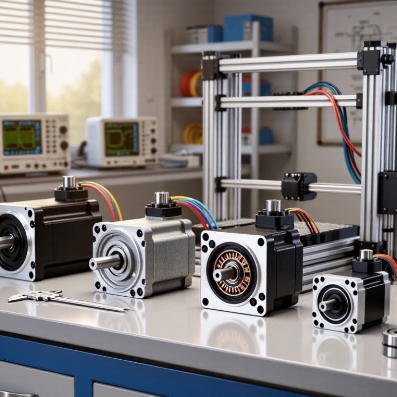
Choosing a precision motor starts with defining the application, not browsing specifications. Write down the required speed, torque, positioning accuracy, repeatability, and movement profile. A motor moving a camera stage differs greatly from one driving a conveyor.
Measure the real load, including friction, inertia, cable drag, and unexpected resistance. Record acceleration and deceleration times. A 2 kg mechanism may demand several times its running torque during startup. Duty cycle matters too. Continuous operation creates heat, while short movements may permit higher peak torque. I have seen designs fail because the calculated load ignored a small gearbox seal.
Operating conditions need equal attention. Note ambient temperature, humidity, dust, vibration, mounting direction, and available space. In a clean laboratory, passive cooling may be sufficient. Near a cutting machine, sealed construction and stronger feedback protection may be necessary. Check whether the motor must hold position during power loss. That requirement changes the control and safety design.
Do not trust nominal values alone. Compare torque-speed curves, thermal limits, encoder resolution, and controller compatibility. Test the motor under the actual load, at the highest expected temperature. Allow margin, but avoid excessive oversizing, which can reduce responsiveness and waste energy. My own early selections sometimes favored impressive peak torque over usable continuous performance. That mistake is easy to repeat. Keep measured results, assumptions, and changes in one requirements sheet.
How to Choose the Right Precision Motor?
Motor selection starts with the motion profile, not the product catalog. Define travel distance, peak speed, acceleration, duty cycle, and load inertia. A compact stepper motor suits repeatable indexing with modest speed and torque demands. It is simple and cost-effective, but missed steps can remain invisible. A servo motor adds feedback, stronger overload performance, and accurate positioning during changing loads. For smooth continuous motion, a brushless motor may offer better efficiency and lower acoustic noise.
The control method must match the machine’s behavior. Open-loop control can work for predictable loads and short moves. Closed-loop control is safer when friction, temperature, or payload changes frequently. Field experience shows that aggressive acceleration often creates more trouble than insufficient motor power. Belt stretch, backlash, and poorly tuned gains can defeat an expensive feedback system. Test the complete mechanism, not only the motor.
Industry data supports careful sizing. The International Federation of Robotics reported 541,302 industrial robots installed worldwide in 2023, showing continued demand for reliable motion systems. The U.S. Department of Energy identifies motor-driven systems as major industrial electricity users, making efficiency and standby losses important selection factors. A practical review should compare torque-speed curves, encoder resolution, thermal limits, controller bandwidth, and maintenance access. Do not trust a single calculation. Real loads are rarely perfect. Allowing reasonable torque margin is wise, but excessive oversizing can reduce responsiveness, efficiency, and control quality.
Choosing a precision motor starts with the load, not the catalog. Torque must cover acceleration, friction, gravity, and unexpected resistance. Calculate continuous and peak torque separately. A motor that survives one peak may still overheat during repeated cycles. The IEA’s Energy Efficiency 2023 report estimates that electric motor systems consume about 50% of global electricity. Efficiency matters, but control quality matters too. Check speed at the real load, not at no-load conditions. A 3,000 rpm rating can collapse under inertia, poor tuning, or weak power delivery. Test the motor across the full operating range.
Accuracy and repeatability are different. Accuracy describes closeness to the commanded position. Repeatability describes returning to the same position. A system can repeat well while remaining consistently offset. ISO 230-2 provides methods for evaluating positioning accuracy and repeatability, including reversal errors and measurement uncertainty. Use those ideas during acceptance testing. Record position errors, settling time, temperature, and payload. Small details matter.
Torque ripple can appear as vibration on a camera axis or uneven motion on a dispensing mechanism. Encoder resolution alone will not fix mechanical backlash. This is often overlooked. Select the coupling, gearbox, bearings, and controller as one system. Leave thermal headroom. A 20% safety margin is useful, but not universal. It may be excessive for a light, fast axis and insufficient for shock loads. Review the assumptions again. That uncomfortable step prevents expensive surprises.
Evaluate torque, speed, accuracy, and repeatability against the requirements of your motion system.
The chart uses a normalized selection index based on common engineering targets: 1.0 N·m torque, 3,000 rpm speed, 0.10° positioning accuracy, and 0.010 mm repeatability. Torque and speed are higher-is-better measures, while accuracy and repeatability are lower-is-better measures. Values represent brand-neutral reference specifications for typical motor classes.
How to Choose the Right Precision Motor?
A precision motor should fit the machine, not just the specification sheet. Check its diameter, length, shaft size, and mass first. A motor that barely fits may create heat, vibration, or service problems. Mounting matters too. Confirm the flange pattern, bolt depth, cable direction, and allowable shaft load. In commissioning work, small mounting errors often appear as positioning noise. They are easy to underestimate.
Feedback determines how accurately the motor can report motion. Encoders provide position data, while resolvers can tolerate harsher environments. Match feedback resolution with the controller, connector, signal type, and communication protocol. According to the International Federation of Robotics’ World Robotics 2024 report, 541,302 industrial robots were installed globally in 2023. This scale increases the need for dependable motion feedback and repeatable maintenance. More resolution is not always better. It can increase cost and integration effort.
Tips: Test the complete motor, drive, controller, and load together. Check continuous torque, peak torque, speed, duty cycle, and braking needs. Review the manufacturer’s thermal curves, not only headline ratings. A useful reality check is cable routing under movement. I have seen a perfect motor selection fail because the cable bent too tightly. That mistake was preventable. Also verify system compatibility before ordering samples. Interfaces can change. Datasheets sometimes leave practical gaps. When uncertain, measure the actual load and leave a sensible thermal margin.
| Motor Type | Typical Frame / Size | Common Mounting | Typical Feedback | Typical Speed Range | Positioning Characteristics | System Compatibility | Best-Fit Applications |
|---|---|---|---|---|---|---|---|
| Stepper Motor | Approx. 20–110 mm square frame; compact versions are also available | Front-flange mounting; face, rear, and custom mounting options may be available | Usually open-loop; optional encoder for stall detection or closed-loop correction | Typically 0–1,500 rpm, depending on load, voltage, and drive settings | High incremental resolution; torque decreases as speed rises; can lose position if overloaded without feedback | Pulse-and-direction or fieldbus stepper drive; requires correct current, voltage, microstepping, and acceleration settings | Indexing tables, laboratory equipment, printers, valves, and moderate-speed automation |
| AC or DC Servo Motor | Approx. 40–180 mm frame size; selected by continuous and peak torque | Standard flange, face mount, or shaft-mounted configurations; dimensions must match the machine interface | Incremental or absolute encoder; resolver options may be used in demanding environments | Commonly 1,000–6,000 rpm; application-specific models may operate outside this range | Closed-loop control provides accurate position, speed, and torque regulation with overload monitoring | Dedicated servo amplifier; confirm feedback protocol, motor current, bus voltage, tuning functions, and command interface | Robotics, CNC axes, packaging machinery, pick-and-place systems, and high-dynamic motion control |
| Brushless DC Motor | Approx. 20–130 mm diameter or equivalent frame; determined by power and thermal requirements | Round flange, face mount, or custom mechanical mounting; shaft and bearing loads must be checked | Hall sensors for commutation; optional incremental encoder or magnetic sensor for precise control | Commonly 1,000–10,000 rpm, depending on winding, voltage, and mechanical load | Efficient and low-maintenance; precise positioning requires a suitable controller and feedback device | Three-phase electronic commutation drive; verify Hall sequence, phase wiring, voltage, current, and control signals | Fans, pumps, spindles, compact actuators, medical equipment, and continuous-speed applications |
| Voice Coil Motor | Typically 10–80 mm active diameter or compact linear assembly | Direct linear mounting with guided moving platform; external bearings or flexures are normally required | Linear encoder, optical sensor, or position sensor for closed-loop operation | Short-stroke motion; speed is application-dependent and limited by stroke, force, and thermal duty cycle | Direct-drive linear force with no mechanical transmission backlash; continuous holding force is limited by heating | Current-controlled linear amplifier; requires a compatible position sensor and motion controller | Optical focusing, precision shutters, semiconductor inspection, micro-positioning, and short-stroke actuators |
| Torque Motor | Large hollow or pancake-style diameter; commonly selected by torque, bore, and allowable heat dissipation | Direct flange or integrated rotary table mounting; precision bearings and a rigid structure are essential | High-resolution optical or magnetic encoder; absolute feedback is useful for position recovery | Often below 3,000 rpm; optimized for high torque at low or moderate speed | Direct drive eliminates gearbox backlash and mechanical wear; excellent for smooth rotary positioning | Three-phase servo drive with compatible encoder interface, current capacity, cooling, and control-loop bandwidth | Rotary stages, gimbals, indexing tables, wafer handling, and precision angular positioning |
Choosing a precision motor starts with the operating profile, not the catalogue price.
The International Energy Agency estimates that electric motor systems consume about 53% of global electricity. Even small efficiency losses can therefore become expensive over years. Record speed, torque, duty cycle, ambient temperature, and peak load from real production data. Laboratory ratings may not match a dusty, stop-start machine.
Efficiency must be measured beside reliability. The U.S. Department of Energy’s Motor Systems Market Assessment reports that motor-driven equipment uses more than half of industrial electricity in the United States. Select a motor that operates near its efficient load range, with suitable thermal capacity and feedback accuracy. Check bearing life, encoder protection, vibration limits, and ingress protection. Ask for test conditions. Numbers without conditions mislead.
Cost analysis should include energy, controls, maintenance, spare parts, and downtime. A cheaper motor can become costly after repeated alignment work or difficult repairs. Request documented failure data, service response times, and replacement lead times. Long-term support matters more than polished launch materials. In practice, I would test one unit under actual loads before a full rollout. It costs extra time. That caution may prevent a much larger mistake. Industry reports guide decisions, but site measurements should challenge them when conditions differ.
Start with the actual load, not the catalog. Calculate continuous and peak torque separately. Include acceleration, friction, gravity, and unexpected resistance.
Rated speed often describes no-load performance. Check speed under real inertia, tuning, and power conditions. Test the entire operating range. Test it loaded.
Accuracy means reaching the commanded position. Repeatability means returning to the same position. A system may repeat precisely while staying consistently offset.
Record position error, settling time, temperature, and payload. Test forward and reverse movement. Small errors can become expensive later.
Torque ripple may cause vibration on a camera axis or uneven dispensing. Encoder resolution alone cannot remove mechanical backlash. The mechanics need review too.
A 20% margin can be useful, but it is not universal. Repeated cycles may cause overheating after one successful peak. Margins are not magic.
Check diameter, length, shaft size, mass, flange pattern, bolt depth, and cable direction. Confirm allowable shaft loads. A tight fit can create heat and vibration.
Match the feedback device with the controller, connector, signal type, and communication method. More resolution may increase cost and integration effort. More is not always better.
Yes. Test the motor, drive, controller, coupling, gearbox, bearings, and load together. Review thermal curves, duty cycle, braking, and cable movement. Perfect specifications can still fail in practice.
Choosing the right Precision Motor begins with a clear understanding of the application’s requirements and operating conditions. Consider the required load, duty cycle, environmental factors, available power, and expected operating life. Next, compare suitable motor types, motion profiles, and control methods to determine which combination can deliver the desired movement smoothly and consistently. Torque, speed, positioning accuracy, and repeatability should be evaluated under real operating conditions rather than relying only on nominal specifications.
It is also important to confirm that the motor fits the available space and mounting arrangement, while remaining compatible with the drive, controller, power supply, and feedback system. Features such as encoder resolution and communication support may significantly affect overall performance. Finally, assess efficiency, reliability, maintenance needs, total cost, and long-term technical support. A well-balanced decision should consider not only initial purchase price but also energy consumption, downtime risk, integration effort, and future system requirements.
