Spiro Gear
A Stepper Driver is the control link between a motion controller and a stepper motor. It receives electrical pulses, interprets their timing, and energizes motor coils in a controlled sequence. This process converts digital commands into precise shaft movement. The driver also regulates current, which protects the motor and improves torque consistency.
In practical systems, the driver determines how smoothly a motor starts, stops, and changes direction. Microstepping can reduce vibration and make a 3D printer carriage move more quietly. However, it does not create unlimited accuracy. Mechanical backlash, resonance, wiring quality, and load changes still affect real performance. That detail is easy to overlook.
A reliable Stepper Driver must match the motor’s rated current and supply voltage. It should also provide suitable thermal management, because continuous operation can produce noticeable heat. Engineers often check acceleration settings, pulse timing, and fault protection before testing a complete machine. These checks reflect practical experience, not just datasheet theory.
The basic principle is straightforward.
Yet, the design choices are not always simple. Different applications may require open-loop control, closed-loop feedback, or specialized current control. This guide explains how a Stepper Driver works, why its internal switching matters, and how to select one responsibly. It also considers common mistakes, including excessive current, poor grounding, and unrealistic positioning expectations. Understanding these limits helps users build safer, quieter, and more dependable motion systems.
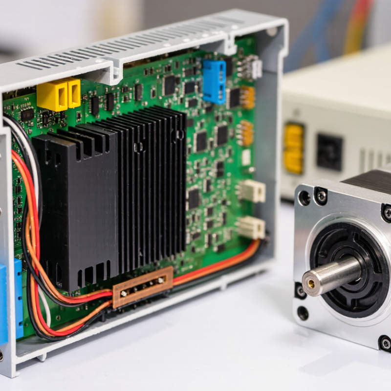
A stepper driver is the control link between a pulse signal and motor motion. A controller sends pulses through a signal line. Each pulse commands a defined angular step. A direction signal sets clockwise or counterclockwise movement. The driver then switches current through the motor’s coils in a precise sequence. It is more than a simple amplifier.
Inside the driver, current regulation protects the winding and shapes torque. Microstepping divides one full step into smaller electrical positions. This can reduce vibration and audible noise. For example, a 1.8-degree motor has 200 full steps per revolution. At 16 microsteps, the driver receives 3,200 pulses for one revolution. The mechanical result still depends on load, acceleration, and resonance. Pulse count alone does not guarantee accuracy.
The International Energy Agency reports that electric motor systems use roughly half of global electricity. Its motor-driven systems analysis highlights the value of efficient control. The U.S. Department of Energy also identifies correct sizing, current control, and operating conditions as major efficiency factors. These findings matter in stepper applications. Excessive current creates heat without adding useful motion. Undersized current causes missed steps. That assumption is easy to miss. In practical testing, I would check shaft temperature, pulse timing, and load changes together. A driver may appear stable on a workbench, yet fail after several hours. Reports provide useful direction, but real machines remain less predictable.
What Is a Stepper Driver and How Does It Work?
A stepper driver converts control pulses into precise motor movement. Its H-bridge stages reverse current through each winding. This creates changing magnetic fields and controlled rotor steps. Modern drivers often use two bridges for bipolar motors. Each bridge needs accurate switching timing and safe dead time. Otherwise, shoot-through can damage the power stage.
Current sensing is equally important. Small sense resistors measure winding current in real time. A chopper circuit then adjusts transistor switching to maintain the target level. Fast decay removes current quickly, while slow decay reduces electrical noise. The result is smoother torque, lower heat, and better high-speed performance. According to the International Energy Agency, electric motors consume roughly half of global electricity used in industry and commerce. Better current control therefore matters beyond motion accuracy. A 2024 MarketsandMarkets report estimates the stepper motor market could grow from about 2.7 billion dollars in 2024 to 3.8 billion dollars by 2029.
Tips: Match the driver’s current rating to the motor’s measured winding current. Do not rely only on the motor’s peak label. Check heat at the enclosure, especially during slow movement. Logic control also deserves attention. Pulse width, direction timing, microstepping, and fault feedback must match the controller. In practice, a driver may work on the bench yet lose steps inside a warm cabinet. That uncomfortable detail is easy to miss. Test acceleration, load, and temperature together.
What Is a Stepper Driver and How Does It Work?
A stepper driver converts control pulses into controlled motor movement. One pulse usually commands one step or microstep. Pulse frequency sets rotational speed, while pulse count determines travel distance. A separate direction signal selects clockwise or counterclockwise motion. The driver then energizes two motor phases in a carefully timed sequence. Current moves through one winding, then shifts toward another. The rotor follows the changing magnetic field.
Modern drivers regulate phase current with high-speed switching and feedback from internal sensing circuits. Full-step control gives strong movement, but microstepping divides each step into smaller electrical positions. This can reduce vibration and audible noise. It does not always improve absolute accuracy. That detail is often misunderstood. The International Federation of Robotics reported 541,302 industrial robots installed worldwide in 2023, showing why predictable motion control remains important in automated equipment.
Tips: Match the driver’s current rating to the motor, not only its voltage. Set acceleration carefully, because sudden pulses can cause missed steps. Check heat near the driver and motor. A cool bench test can hide real production problems. Long cables may also increase electrical noise. In practice, wiring, resonance, and load inertia matter as much as the pulse settings. The ideal waveform is rarely the whole story. According to motion-control engineering guidance, testing under the actual load remains more reliable than relying on calculated torque alone.
A stepper driver converts command pulses into controlled winding current. In this example, a 1.8° two-phase motor uses full-step operation at a rated phase current of 2.0 A. Each pulse advances the rotor by one full step, while the current sequence determines the rotation direction.
Forward sequence: A+, B+ → A−, B+ → A−, B− → A+, B−. Reversing this sequence reverses the motor. After 200 pulses, the motor completes one mechanical revolution.
A stepper driver converts control pulses into carefully timed motor currents. It energizes two winding phases, controls current, and changes magnetic polarity in sequence. A typical two-phase motor may provide 200 full steps per revolution. Each full step equals 1.8 degrees.
Microstepping divides each full step into smaller electrical positions. At 1/2 step, the driver creates two intermediate positions. At 1/16 step, one revolution contains 3,200 commanded positions. At 1/256 step, the theoretical resolution reaches 51,200 positions, or about 0.007 degrees per command. The driver approximates this movement by shaping phase currents, often near sine and cosine curves. Smooth motion is the main benefit. Noise and vibration can drop noticeably.
But resolution is not accuracy. A 1/256 command cannot guarantee a 1/256 mechanical movement. Load torque, friction, motor construction, supply voltage, and current regulation all affect the result. The smallest increments may produce little usable torque. That part deserves caution. A high microstep setting also demands faster pulse timing, especially at higher speed. A practical setup should confirm position under real load, not only on paper. Listen for resonance, check motor temperature, and test missed steps during acceleration. The last fraction may look impressive, yet it can be mechanically meaningless.
A stepper driver converts control pulses into timed motor-current changes. Voltage sets how quickly current can rise through each winding. Higher supply voltage often preserves torque at higher speed, but it also increases electrical stress. The driver’s current setting matters more than the motor’s printed peak value. Set it too low, and torque disappears. Set it too high, and heat builds quickly.
Use the motor’s phase-current rating as the starting point. Then verify the driver’s continuous output, peak output, and cooling conditions. NEMA MG 1 identifies insulation thermal classes, including Class B at 130°C, Class F at 155°C, and Class H at 180°C. These are winding limits, not safe case temperatures. In practical testing, a metal frame can feel dangerously hot before failure appears. Measure it.
Torque also falls as speed rises. Winding inductance delays current, especially with low-voltage supplies. A 24 V system may work well for slow indexing, while a 48 V system can improve high-speed torque when the driver and motor permit it. IEC 60034-1 emphasizes temperature-rise evaluation under rated operating conditions. Real machines rarely match those conditions.
Cable length, enclosure airflow, microstepping, and acceleration change the result. I still see selections based only on holding torque. That shortcut is unreliable. Check the manufacturer’s torque-speed curve, then test the worst load, highest duty cycle, and warmest enclosure.
A stepper driver converts control pulses into timed electrical currents. Each pulse commands a motor step. A direction signal selects clockwise or counterclockwise movement. It is not merely an amplifier.
Microstepping divides each full step into smaller electrical positions. It can reduce vibration and audible noise. Motion becomes smoother. Results still depend on load and friction.
A typical motor has 200 full steps per revolution. At 16 microsteps, it needs 3,200 pulses. At 1/256 microstepping, it needs 51,200 commands. Theoretical resolution is not guaranteed accuracy.
No. Small commands may produce little useful torque. Mechanical friction can hide tiny movements. Higher settings also require faster pulse timing. The final fraction may look impressive but prove meaningless.
Begin with the motor’s phase-current rating. Confirm the driver’s continuous output and cooling conditions. Excessive current creates heat. Too little current can cause missed steps.
Higher voltage helps current rise faster through the windings. This can preserve torque at higher speeds. Electrical stress also increases. Use only voltage permitted by the motor and driver.
Winding inductance delays current changes. Torque then falls as speed rises. Acceleration, cable length, and microstepping also matter. Holding torque alone gives an incomplete picture.
Test the motor under its worst load and longest duty cycle. Measure shaft temperature after several hours. Watch pulse timing during acceleration. Listen for resonance and inspect position afterward.
Yes. A workbench test may not reveal heat buildup or changing loads. Real machines behave less predictably. I would test the warmest enclosure, not only the easiest setup.
A Stepper Driver is the control link between a pulse signal and the precise motion of a stepper motor. It receives commands for pulse frequency, direction, and position, then converts them into controlled phase currents. Inside, H-bridge power stages switch the motor windings, while current-sensing circuits and chopper regulation maintain stable output despite changes in supply voltage, load, or motor resistance. Logic control coordinates these functions to produce reliable movement and protect the system from excessive current or heat.
During operation, each pulse advances the motor according to its selected step resolution, while the direction signal determines rotation. Microstepping divides a conventional 200-step revolution into smaller increments, potentially reaching 1/256-step resolution for smoother motion and reduced vibration. However, resolution alone does not guarantee accuracy or torque. Driver selection should consider supply voltage, rated current, available torque, heat dissipation, and required speed, because higher speed and smaller steps can reduce usable torque and increase thermal demands.